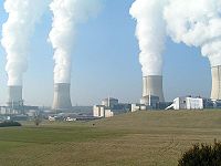
Industrial cooling tower
Industrial cooling towers are heat rejection systems used primarily to provide circulating cooling water in large industrial facilities. The circulating cooling water absorbs heat by cooling and/or condensing the hot process streams or by cooling hot rotating machinery and other hot equipment within the industrial facilities. The cooling towers then reject that absorbed heat by transferring it to the atmosphere.
How a cooling tower works
Basically, a cooling tower intimately contacts a flow of warm water with a flow of ambient air which is not saturated with water vapor (i.e, air which contains less water vapor than it is capable of containing). That causes part of the warm water to evaporate and the air absorbs that evaporated water. The heat required to evaporate part of the water is derived from the water itself and thus causes the water to cool. This process is known as evaporative cooling.[1][2] The net result is that the air leaving the tower is saturated with water vapor and the unevaporated water leaving the cooling tower has been cooled.
An evaporative cooling tower is referred to as a wet cooling tower or simply a cooling tower. Such towers can cool water to a temperature that approaches the wet-bulb temperature of the ambient air. The average ambient air wet-bulb temperature chosen as the design basis essentially determines the size of the cooling tower, and the size of a cooling tower is inversely proportional to the design wet-bulb temperature.
To achieve better performance (more cooling), a media called fill is used to increase the contact surface area between the air and water flows. Splash fill consists of material placed to interrupt the water flow causing splashing. Film fill is composed of thin sheets of material upon which the water flows.[3] Most fill in modern cooling towers is plastic material.
Applications
The primary use of large, industrial cooling towers is to remove the heat absorbed in the circulating cooling water systems used in industrial facilities such as petroleum refineries, petrochemical and chemical plants, natural gas processing plants, fossil-fuel power plants and nuclear power plants.
The circulation rate of cooling water in a typical 700 MW conventional coal-fired power plant with a cooling tower amounts to about 71,600 cubic metres an hour (315,000 U.S. gallons per minute)[4] and the system requires a supply water make-up rate of perhaps 5 percent (i.e., 3,600 cubic metres an hour). The largest users of cooling water in a power plant are the surface condensers that condense the exhaust steam from the large steam turbines that drive the electrical generators.
If that same plant had no cooling tower and used once-through cooling water, it would require about 100,000 cubic metres an hour [5] and that amount of water would have to be continuously returned to the ocean, lake or river from which it was obtained and continuously re-supplied to the plant. Furthermore, discharging large amounts of hot water may raise the temperature of the receiving river or lake to an unacceptable level for the local ecosystem. A cooling tower serves to dissipate the heat into the atmosphere instead and wind and air diffusion spreads the heat over a much larger area than hot water can distribute heat in a body of water.
Some coal-fired and nuclear power plants located in coastal areas do make use of once-through ocean water. But even there, the offshore discharge water outlet requires very careful design to avoid environmental problems.
Petroleum refineries also have very large cooling tower systems. A typical large refinery processing 40,000 metric tonnes of petroleum crude oil per day (300,000 barrels per day) circulates about 80,000 cubic metres of water per hour through its cooling tower system.
This article is devoted to the large-scale cooling towers used in industrial facilities. However, much smaller cooling towers of various types are used in the air-conditioning of office buildings, hotels, sports arenas, food storage facilities and many other commercial establishments.
Cooling tower operational variables
Quantitatively, the material balance around a wet, evaporative cooling tower system is governed by the operational variables of makeup flow rate, evaporation and drift losses, blowdown rate, and the concentration cycles:[6]
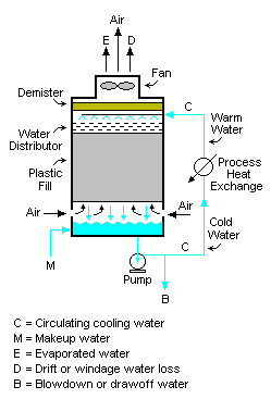
Referring to Figure 3, water pumped from the cooling tower basin is the cooling water routed through the process stream cooling and condensing heat exchangers in an industrial facility. The cool water absorbs heat from the hot process streams which need to be cooled or condensed, and the absorbed heat warms the circulating water (C).
The warm water returns to the top of the cooling tower and trickles downward over the fill material inside the tower. As it trickles down, it contacts the fan-induced upward flow of ambient air. That contact causes a portion of the water (E) to evaporate into water vapor that exits the tower as part of the water saturated air. A small amount of the water also exits as entrained liquid water called drift losses (D). The heat required to evaporate the water is derived from the water itself, which cools the water back to the original basin water temperature and the water is then ready to recirculate.
The evaporated water leaves its dissolved salts behind in the bulk of the water which has not been evaporated, thus raising the salt concentration in the circulating cooling water. To prevent the salt concentration of the water from becoming too high, a portion of the water, referred to as blowdown (B) is drawn off for disposal. Fresh water makeup (M) is supplied to the tower basin to compensate for the loss of evaporated water, the drift loss water and the blowdown water.
Defining the various terms:
| M | = Make-up water in m³/hr |
| C | = Circulating water in m³/hr |
| B | = Blow-down water in m³/hr |
| E | = Evaporated water in m³/hr |
| D | = Drift loss of water in m³/hr |
| X | = Concentration in ppmw (of any completely soluble salts … usually chlorides) |
| XM | = Concentration of chlorides in make-up water (M), in ppmw |
| XC | = Concentration of chlorides in circulating water (C), in ppmw |
| Cycles | = Cycles of concentration = XC / XM (dimensionless) |
| ppmw | = parts per million by weight |
A water balance around the entire system is:
- M = E + D + B
Since the evaporated water (E) has no salts, a chloride balance around the system is:
- M (XM) = D (XC) + B (XC) = XC (D + B)
and, therefore:[6]
- XC / XM = Cycles of concentration = M ÷ (D + B) = M ÷ (M – E) = 1 + [E ÷ (D + B)]
From a simplified heat balance around the cooling tower:[6]
- E = C · ΔT · cp ÷ HV
| where: | |
| HV | = latent heat of vaporization of water = ca. 2260 kJ / kg |
| ΔT | = water temperature difference from tower top to tower bottom, in °C |
| cp | = specific heat of water = ca. 4.184 kJ / (kg°C) |
Modern cooling towers have demisters known as drift eliminators to reduce the amount of drift losses (D) from large-scale industrial cooling towers. However, some older cooling towers have no drift eliminators. In the absence of manufacturer's data, drift losses may be assumed to be:
- D = 0.3 to 1.0 percent of C for a natural draft cooling tower without drift eliminators
- D = 0.1 to 0.3 percent of C for an induced draft cooling tower without drift eliminators
- D = about 0.005 percent of C (or less) if the cooling tower has drift eliminators
Cycles of concentration represents the accumulation of dissolved minerals in the recirculating cooling water. Blowdown of a portion of the circulating water (from the tower basin) is the principal means of controlling the buildup of these minerals.
The chemistry of the makeup water including the amount of dissolved minerals can vary widely. Makeup waters low in dissolved minerals such as those from surface water supplies (lakes, rivers etc.) tend to be aggressive to metals (corrosive). Makeup waters from ground water supplies (wells) are usually higher in minerals and tend to be scaling (deposit minerals).
As the cycles of concentration increase, the water may not be able to hold the minerals in solution. When the solubility of these minerals have been exceeded they can precipitate out as mineral solids and cause fouling and heat exchange problems in the cooling tower or the heat exchangers. The temperatures of the recirculating water, piping and heat exchange surfaces determine if and where minerals will precipitate from the recirculating water. Often a professional water treatment consultant will evaluate the makeup water and the operating conditions of the cooling tower and recommend an appropriate range for the cycles of concentration. The use of water treatment chemicals, pretreatment such as water softening, pH adjustment, and other techniques can affect the acceptable range of cycles of concentration.
Concentration cycles in the majority of cooling towers usually range from 3 to 7. In the United States the majority of water supplies are well waters and have significant levels of dissolved solids. On the other hand one of the largest water supplies, New York City, has a surface supply quite low in minerals and cooling towers in that city are often allowed to concentrate to 7 or more cycles of concentration.
Besides treating the circulating cooling water in large industrial cooling tower systems to minimize scaling and fouling, the water should be filtered and also be dosed with biocides and algaecides to prevent growths that could interfere with the continuous flow of the water.[6] Corrosion inhibitors may also be used, but caution should be taken to meet local environmental regulations as some inhibitors use chromates.
Types of cooling towers
Wet cooling towers may be categorized by their method of generating air flow, by their air-to-water flow arrangement and by their physical shape.
Air flow generation methods
With respect to generating air flow through the tower, there are three types of cooling towers:
- Natural draft,[7]which uses the so-called stack effect of a tall flue gas stack or other enclosed structure where the warm inside air naturally rises due to the density differential between that inside warm air and the cooler outside air. Thus, the buoyancy of the inside air relative to the outside air induces a flow of air through the cooling tower.
- Mechanical draft, which uses motor-driven fans to either force or draw air through the tower.
- Induced draft, which uses a fan at the air exit from the cooling tower to pull or draw air through the tower. This produces low entering and high exiting air velocities, reducing the possibility of the exit air recirculating back into the air intake.
- Forced draft: which uses a fan at the air intake to the cooling tower to push or force air through the tower. This produces high entering and low exiting air velocities. The low exiting velocity is more susceptible to recirculation. Also, a fan on the cold air intake more susceptible to complications due to freezing conditions than is a fan on the warm air exit.
Air-to-water flow arrangements
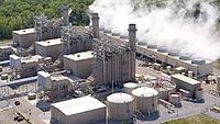
- Counterflow is an arrangement, as in Figure 3, in which the air flows upward through the fill and the water flows downward through the fill. Figure 1 is a photograph of a fan-induced draft, counterflow cooling tower in a power plant operated by the Tennessee Valley Authority (TVA).
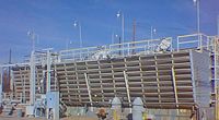
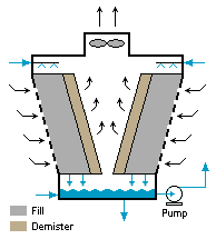
- Crossflow is an arrangement, as in Figure 4, in which the air flow is directed perpendicular to the water flow. Figure 2 is a photograph of a fan-induced draft, cross-flow cooling tower. Air flow enters one or more vertical faces of the cooling tower and flows horizontally through the fill material. Water flows downward (perpendicular to the air) through the fill.
Both crossflow and counterflow designs can be used in natural draft and mechanical draft cooling towers.
Physical shapes
Cooling towers may have a rectangular box shape as depicted in Figures 1 and 3. Most petroleum refineries, natural gas processing plants, and petrochemical or chemical plants use rectangular box shaped cooling towers.
Cooling towers may also have a hyperboloid shape as shown in Figure 5.[7] Hyperboloid (or hyperbolic) cooling towers have become essentially the design standard for natural-draft cooling towers because of their structural strength and minimum usage of material. The air-to-water flow arrangement within hyperboloid cooling towers may be counterflow or crossflow and the air flow may be fan assisted, just as in the rectangular box shaped cooling towers. The hyperbolic form is popularly associated with nuclear power plants. However, this association is misleading, as they are often used at large coal-fired power plants as well.
Large rectangular box cooling towers can be up to 40 metres tall and 175 metres long. The hyperboloid cooling towers can be up to 200 metres tall. The cooling tower at the coal-fired power plant in Niederaussen, Germany is 200 metres high and the water basin at the bottom of the tower has a diameter of 141 metres. It was said to be the largest cooling tower in the world as of 2004.[7]
Some commonly used terms in the cooling tower industry
- Drift - Water droplets that are carried out of the cooling tower with the exhaust air. Drift droplets have the same concentration of impurities as the water entering the tower. The drift rate is typically reduced by devices, called drift eliminators, through which the air must travel after leaving the fill and water spray zones of the tower.
- Plume - The stream of saturated exhaust air leaving the cooling tower. The plume is visible when the water vapor it contains condenses in contact with cooler ambient air. Under certain conditions, a cooling tower plume may present fogging or icing hazards to its surroundings.
- Blow-down - The portion of the circulating water flow that is removed in order to maintain the amount of dissolved solids and other impurities at an acceptable level.
- Leaching - The loss of wood preservative chemicals by the washing action of the water flowing through a wood cooling tower structure.
- Approach - The approach is the difference in temperature between the cooled-water temperature and the wet-bulb temperature of the ambient air entering the tower. Since the cooling towers are based on the principles of evaporative cooling, the maximum cooling tower efficiency depends on the wet bulb temperature of the air.
- Range - The range is the temperature difference between the water inlet and water exit.
- Fill - Inside the tower, fills are added to increase the contact surface between the air and the water. Thus, they provide better heat transfer. The efficiency of the tower also depends on them.
Legionnaires' disease
Legionellosis (referred to as Legionnaires' disease) is a dangerous infectious disease caused by bacteria belonging to the genus Legionella. In many outbreaks of that disease, air-conditioning cooling towers have been found to be the source of the disease-causing bacteria.
Many governmental agencies, cooling tower manufacturers and industrial trade organizations have developed design and maintenance guidelines for preventing or controlling the growth of Legionella in cooling towers.[8] [9] [10] [11]
References
- ↑ Larry Drbal, Kayla Westra and Pat Boston (1996). Power Plant Engineering, 1st Edition. Springer. ISBN 0-412-06401-4.
- ↑ Robert H. Perry (deceased), Don W. Green and James O. Maloney (Editors) (1984). Perry's Chemical Engineers' Handbook, 6th Edition. McGraw-Hill. ISBN 0-07-049479-7.
- ↑ Cooling tower fill
- ↑ Cooling System Retrofit Costs EPA Workshop on Cooling Water Intake Technologies, John Maulbetsch and Kent Zammit, May 2003
- ↑ United States Department of Energy (Office of Fossil Energy's Power Plant Water Management R&D Program)
- ↑ 6.0 6.1 6.2 6.3 Beychok, Milton R. (1967). Aqueous Wastes from Petroleum and Petrochemical Plants, 1st Edition. John Wiley and Sons. LCCN 67019834. (available in many university libraries)
- ↑ 7.0 7.1 7.2 I. Mungan and U. Wittek (Editors) (2004). Natural Draught Cooling Towers. Taylor & Francis Group. ISBN 90-5809-642-4. >
- ↑ SPX (Marley) Cooling Technologies, ASHRAE Guideline 12-2000, //Minimizing the Risk of Legionellosis//
- ↑ Technical Guidelines for Control and Prevention of Travel Associated Legionnaires' Disease, January 2005, European Working Group for Legionella Infections (EWGLI)
- ↑ Guidelines for Environmental Infection Control in Health-Care Facilities, //Procedure for Cleaning Cooling Towers and Related Equipment (pp. 225-226)//, U.S. Centers for Disease Control and Prevention (CDC)
- ↑ Best Practices for Control of Legionella, Cooling Technology Institute
