Ellipse
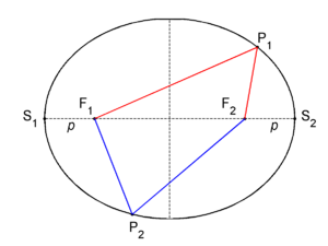
In mathematics, an ellipse is a planar locus of points characterized by having a constant sum of distances to two given fixed points in the plane. In figure 1, the two fixed points are F1 and F2, these are the foci of the ellipse. Consider an arbitrary point P1 on the ellipse that has distance F1P1 to F1 and distance F2P1 to F2, and let d be the sum of distances of P1 to the foci,
then for all points of the ellipse the sum of distances is also d. Thus, for another arbitrary point P2 on the ellipse with distance F1P2 to F1 and distance F2P2 to F2, by definition, the sum of distances of P2 to the foci is equal to d,
The horizontal line segment between S1 and S2 in figure 1, going through the foci, is known as the major axis of the ellipse.[1] Traditionally, the length of the major axis is indicated by 2a. The vertical dashed line segment, drawn halfway between the foci and perpendicular to the major axis, is referred to as the minor axis of the ellipse; its length is usually indicated by 2b. The major and the minor axis are distinguished by a ≥ b.[2]
Clearly both ellipse axes are symmetry axes, reflection about either of them transforms the ellipse into itself. Basically, this is a consequence of the fact that reflection preserves (sums of) distances. The intersection of the axes is the center of the ellipse.
The two foci and the points S1 and S2 are connected by reflection about the minor axis. Hence the distance S2F2 =: p is, by symmetry, equal to the distance S1F1.[3] The distance of S2 to F1 is equal to 2a − p. By the definition of the ellipse their sum is equal to d, hence
The sum d of distances from any point on the ellipse to the foci is equal to the length of the major axis.
Special cases. There are two extreme cases:
(a) The first occurs when the two foci coincide. Then a = b and the ellipse is a circle — a special case of an ellipse — and the coinciding foci are the center of the circle. If, in addition, d = 0 then the circle degenerates to a point. (In a circle, any diameter can be chosen as the major axis or as the minor axis.)
(b) The second extreme case occurs when the distance of the foci equals d. Then b = 0 and the ellipse degenerates to the line segment bounded by the foci.
(Remark: Usually, in common language, these extreme cases are not referred to as an ellipse because "circle" (or "point") and "line segment" describe them better, but in mathematics they are included because they satisfy the definition.)
Conic section
In the work of the Greek mathematician Apollonius (c. 262–190 BC) the ellipse arose as the intersection of a plane with a cone. Apollonius gave the ellipse its name, though the term ἔλλειψις (elleipsis, meaning "falling short") was used earlier by Euclid (c. 300 BC) in the construction of parallelograms with areas that "fell short". Apollonius applied the word to the conic section that at present we call ellipse. See Ref.[4] for the—in modern eyes—complicated reasoning by which Apollonius tied the shape of certain conic sections to Euclid's concept of deficient areas.
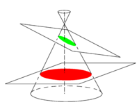
In figure 2 a cone with a circular base is shown. It has a vertical symmetry axis, an axis of revolution. A cone can be generated by revolving around the axis a line that intersects the axis of rotation under an angle α (strictly between 0 and 90 degree). A horizontal plane (plane perpendicular to the axis of the cone) — that does not contain the vertex — intersects the cone in a circle (a special ellipse). A plane that intersects the axis in an angle greater than α intersects the cone in an ellipse. (Otherwise, the intersection is either a parabola or a hyperbola.) If the plane contains the vertex, the ellipse degenerates to a point; if the plane is perpendicular to the axis the ellipse is a circle.
Eccentricity
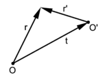
The eccentricity e of an ellipse (usually denoted by e or ε) is the ratio of the distance OF2 (cf. figure 3) to the length a (half the major axis), that is, e := OF2 / a. Let be a vector of length a along the x-axis, then
The following two vectors have common endpoint at P, see figure 3,
Now choose P as the intersection P1 of the positive y-axis with the ellipse; then its position vector is:
By symmetry, the distance of this point P1 to either focus is equal, thus the length of the corresponding vector (with endpoint on the y-axis) is equal to the length a of the semi-major axis. For the following two inner products (indicated by a centered dot) we find,
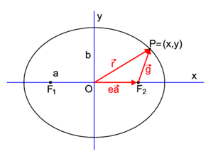
Fig. 3. An ellipse situated such that the major and minor axes are along Cartesian axes. The center of the ellipse coincides with the origin O.
Hence, (in fact the Pythagoras theorem applied to P1OF2),
so that the eccentricity is given by
Remark: The two extreme values for the eccentricity correspond to the extreme forms of an ellipse: The vaule 0 corresponds to the circle, the value 1 to the line segment.
Algebraic form
Consider an ellipse that is located with respect to a Cartesian frame as in figure 3 (a ≥ b > 0, major axis on x-axis, minor axis on y-axis). Then:
(Canonical equation of an ellipse) A point P=(x,y) is a point of the ellipse if and only if
Note that for a = b this is the equation of a circle. An ellipse may be seen as a unit circle in which the x and the y coordinates are scaled independently, by 1/a and 1/b, respectively. (An ellipse degenerated to a line segment cannot be described with such an equation.)
Proof
Part 1: We first consider an arbitrary point P of the ellipse. Introduce the vectors
By definition of ellipse, the sum of the lengths is 2a
Multiplying equation (1) by
gives
-
- Failed to parse (SVG (MathML can be enabled via browser plugin): Invalid response ("Math extension cannot connect to Restbase.") from server "https://wikimedia.org/api/rest_v1/":): {\displaystyle = 4e\vec{r}\cdot\vec{a} }
Hence
and since
(the first coordinate of the vector ) we obtain
By adding and subtracting equations (1) and (2) we find expressions for the distance of P to the foci,
Squaring both equations
adding them, substituting the earlier derived value for e2, and reworking gives
Division by b2 finally gives
Part 2: Conversely, for any point P whose coordinates x and y satisfy this equation, the sum of its distances from the foci
is
To show this we calculate
and substitute for f and
and obtain
After an analogous calculation for F2 we get (note that because and )
as claimed.
Second degree equation
The algebraic form of the previous section describes an ellipse in a special position. Rotation and translation transforms it into an equation of second degree in x and y:
(all variables are real). Such an equation always describes a conic section.
It represents a non-degenerate ellipse (minor axis not 0) if and only if the following conditions are satisfied:
- or, equivalently,
where t1 and t2 are defined as the solutions of the following system of linear equations:
(These equations have a unique solution since, by the first condition, the determinant AC − B2 ≠ 0.)
Proof
We now switch to matrix-vector notation and write f(x,y) as
with
The superscript T stands for transposition (row vector becomes column vector and vice versa).
We first show that the conditions are sufficient:
Since, by assumption, the determinant det(Q) = AC−B2 ≠ 0, the matrix Q is invertible. With the help of the inverse Q−1 the equation for f can be rewritten to
Note that this uses
i.e., that both the matrix Q and its inverse are symmetric.
Define
and
In the definition of t the minus sign is introduced to get the translation of the origin as depicted in figure 4.
Now we substitute r′ in the expression for f. (This corresponds to shifting the origin of the coordinate system to the center of the ellipse):
with
Thus, by translation of the origin over t the linear terms in f(r) have been eliminated, only two quadratic terms (in x′ := x−t1 and y′ := y−t2), one bilinear term, and one constant term (ft) appear in the equation for f. (The "price paid" for it is the requirement det(Q) ≠ 0.)
In the next step we rotate the coordinate system (around the origin in O') such that the coordinate axes coincide with the axes of the ellipse. This will eliminate the bilinear term and "decouple" x′ and y′, the components of r′.
Let us recall that any real symmetric matrix may be diagonalized by an orthogonal matrix. For the (2×2)-case:
where the last matrix on the right is the identity matrix I. Now
with
Switching back to a quadratic equation
we see that an ellipse is obtained if the parameters α1, α2, and ft are non-zero and if the signs of α1 and α2 are equal and opposite to the sign of ft.
It is known that the determinant of a matrix is invariant under similarity transformations, hence
and the signs of α1 and α2 are equal.
The trace A+C of the matrix is also invariant under similarity transformations. Thus
and we can apply the assumption
and conclude that in both cases the second order equation represents an ellipse. This shows that the conditions given are sufficient.
The conditions are also necessary:
In the coordinate system determined by its axes, the equation clearly satisfies the conditions, and — since determinant and trace are preserved — they stay satisfied if the system is rotated and shifted. Thus the conditions are necessary if the determinant is not equal to 0. In fact, it is necessary without this assumption on the determinant (see second-order curve).
Remark
Clearly, in order to determine a priori whether the quadratic equation represents an ellipse,
it is not necessary to actually perform the diagonalization of Q.
It is sufficient to check the condition and determine the sign of ft = f(t)
by solving the equation given for the vector t.
Polar representation relative to focus
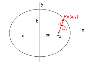
The length g of a vector (cf. figure 5) from the focus F2 to an endpoint P on the ellipse
is given by the polar equation of an ellipse (with eccentricity less than 1)
where 2ℓ is known as the latus rectum (lit. erect side) of the ellipse; it is equal to 2g for θ = 90° (twice the length of the vector when it makes a right angle with the major axis).
Proof
Earlier [Eq. (3)] it was derived for the distance from the right focus F2 to P that
Expressing x from
gives
so that
Substitute
and the polar equation for the ellipse follows.
Trammel construction
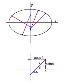
Before drafting was done almost exclusively by the aid of computers, draftsmen used a simple device for drawing ellipses, a trammel. Basically, a trammel is a rigid bar of length a (semi-major axis). In the top drawing of figure 6 the bar is shown as a blue-red line segment bounded by a black and a blue bead. On this bar a segment of length b (semi-minor axis) is marked; this is the red segment on the bar. Two beads fixed to the rigid bar move back and forth along the x-axis and y-axis, respectively. The blue bead fixed at one end of the bar moves along the y-axis, the red bead, which marks the beginning of the red segment of length b, moves along the x-axis. The endpoint of the bar (the black bead in figure 6) moves along an ellipse with semi-major axis a and semi-minor axis b and typically has a pen fixed to it.
The fact that the trammel construction works is proved very easily, cf. the bottom drawing in figure 6,
Hence
which indeed is the equation for an ellipse.
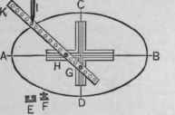
A device called a trammel point is used to guide a woodworking router in making elliptical cuts.
Gardener's construction
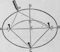
It is possible to construct an ellipse of given major and minor axes by the aid of a compass, a ruler, three thumbtacks, and a piece of string, see figure 8.
First draw the major axis AB, and then obtain with the compass its perpendicular bisector intersecting AB in the midpoint E. Along the bisector one measures off the length of the minor axis CD. Given that the distances CF and CG are the semi-major axis (AB/2), one can determine the foci by drawing an arc with the compass using C as center and AB/2 as radius. One now pins the thumbtacks in the foci and the point C and fixes a piece of string around the triangle FGC (i.e, its length equals the perimeter of the triangle). Removing the thumbtack at C, and keeping the string taut, one draws the ellipse by moving the pencil from C to A, D, B, and back to C.
Clearly this procedure can be used in the garden to create an elliptic lawn or flowerbed, which is why the procedure is sometimes referred to as the gardener's construction.
Notes
- ↑ The points S1 and S2 are the main vertices of the ellipse.
- ↑ The quantities a and b are referred to as semi-major and semi-minor axis, respectively. Note that, just as diameter of circle, semi-axis does not only refer to the line segment itself, but also to its length.
- ↑ The shortest distance of a focus to a point on the ellipse (= p, as can be seen from equation (3), for instance) is the periapsis of the ellipse; the longest distance, S1F2=S2F1=2a−p, is the apoapsis. These two (Greek) terms are mainly used in astronomy when orbits of planets are described.
- ↑ M. Kline, Mathematical Thought from Ancient to Modern Times, Oxford UP, New York (1972)
Figures 7 and 8 are from George Watson Kittredge, The New Metal Worker Pattern Book, David Williams Company, New York, (1901) Online
